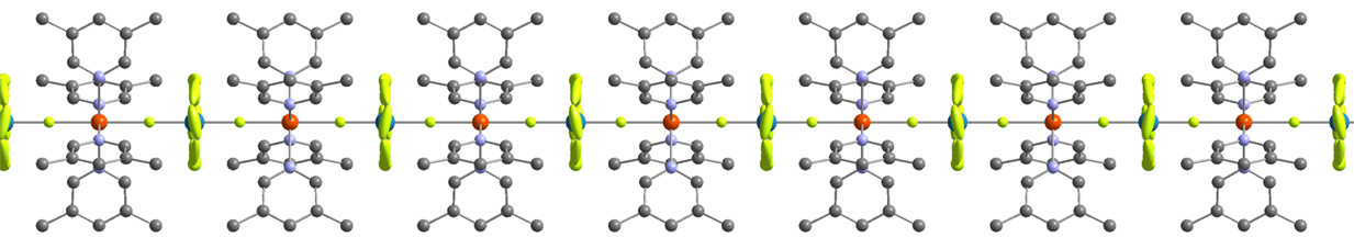
Details on loading samples and pressure transmitting media in diamond anvil cells
Setting Up the Diamond Anvil Cell (DAC)
1) Decrease pressure on the cell to zero. Remember to release the pressure gently by turning each screw in turn by very small amounts. Check the cell under the microscope during this process to make sure that the gasket hole stays in the centre of the diamond culets.
Note: Please take note of safety precautions necessary for the samples and solvent that have been loaded. MSDS sheets and a safety form should be available to users opening a cell so that any safety precautions for the contents are known (although the sample volume is small).
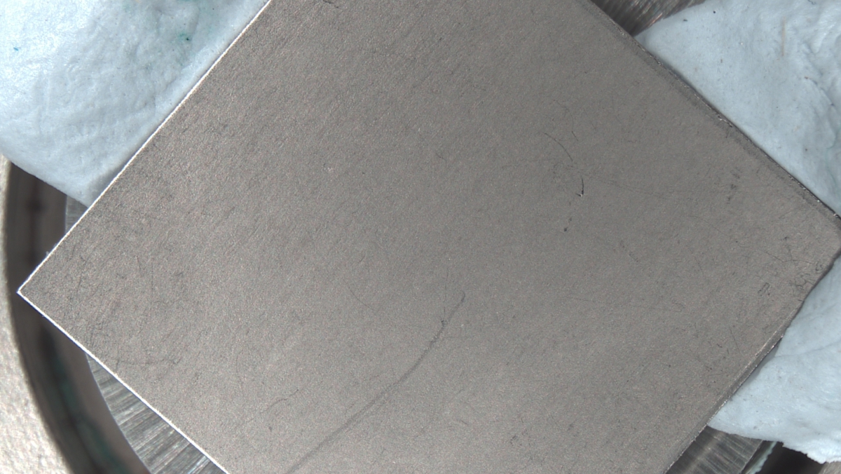
2) Once the screws have been removed, take the top face of the cell off carefully and remove the old gasket. Clean the diamonds thoroughly using a cotton wool bud soaked in ethanol, checking the diamonds under the microscope to make sure they’re clean.
3) Check the alignment of the diamonds - this can be done by looking at the overlay of the culet faces under the microscope and observing whether there is any difference in position.
4) Clean a new gasket thoroughly with ethanol and place on the bottom half of the cell, making sure that there is enough Blu-tac in the right place. Put the top half of the cell on now and put in the screws, tightened to “finger tightness”.
5) Slowly and carefully tighten the screws, a little bit at a time and each in turn as before. Keep checking the cell under the microscope as you go (on the polariser setting). A cross will appear on the diamond which is the stress of the gasket being dented. Watch for bright colours appearing around the edges of the diamond.
CAUTION: During this process, you are most likely to break diamonds. If you’re unsure, please consult a more experienced researcher.
6) Once you think the screws have been tightened enough to achieve an indent in the gasket of about 75-125 microns for a 300 micron thick gasket (this comes with practice by observing the colours and the feel of the screw tightness) slowly release the screws. Take the top of the cell off and mark the gasket so you know which way to replace it.
7) Remove the gasket from the bottom of the cell and check the thickness of the indent using the micrometer. The sample chamber should therefore be 175-225 microns deep.
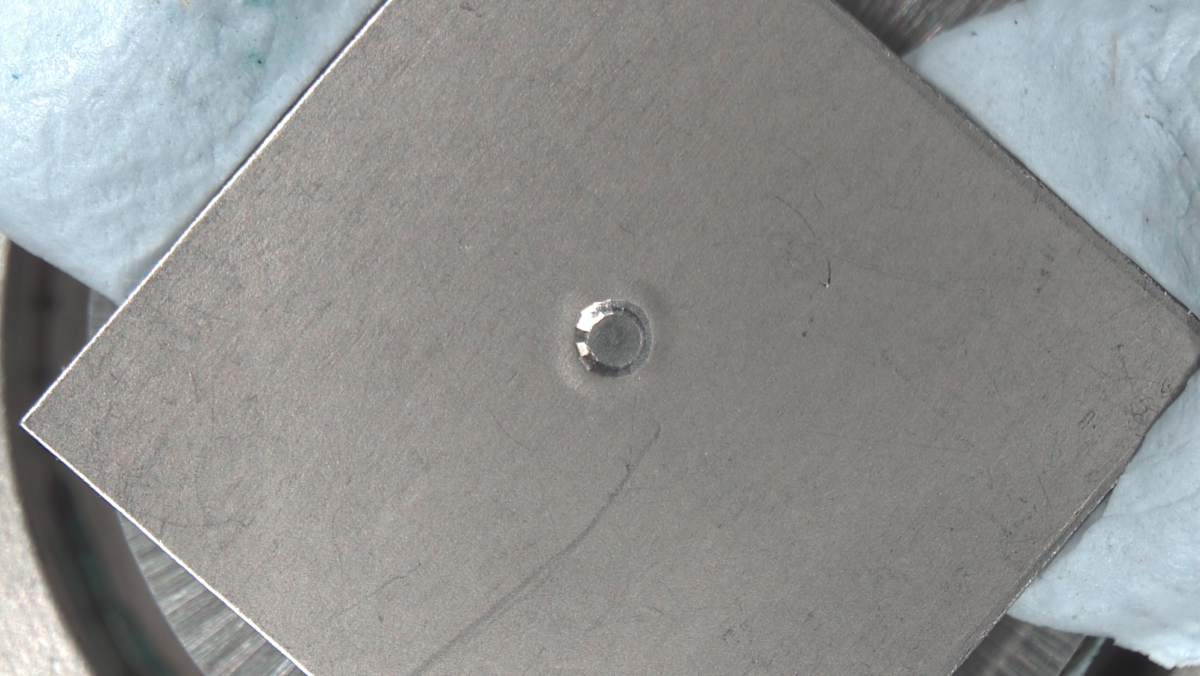
8) If the gasket has the correct size of indent, place it in the bath on the table of the drilling machine and fix it in place with the indent over the hole using the black block to hold the gasket down as flat as possible. MAKE SURE THE MACHINE ISN’T ON OR YOU COULD POTENTIALLY GET AN ELECTRIC SHOCK. Check the drilling wire - is it the right thickness, length and straightness? Check it under the microscope.
9) Next we will align the microscope with the driller and drill a hole in the gasket in the centre of the indent.
a) Move the table so the wire is off to the left of the indent so that the mark you are about to make doesn’t end up in the indent. Then fill up the bath with paraffin or kerosene.
b) WITH THE SPARK ERODER ON, move the table up until there is just contact between the wire and the gasket (the red light just comes on). Move the table back down by ten divisions and then hit the switch. Please read the documentation for the spark eroder so that the correct voltage and current are selected depending on gasket material, whole size and gasket thickness.
c) Once the drill has hit the gasket (the red light comes on) let it drill into the metal about 10 divisions on the dial. Then stop the drill by flicking the switch up and lower the table back to 0. Move the drill away, suck out the paraffin/kerosene and carefully clean the gasket without moving it.
d) Now looking down the microscope, move the table up until the gasket is in focus. Hopefully the mark should be visible, if not you will have to search using the MICROSCOPE KNOBS. Once you have found the mark move it into the centre of the microscope cross-hairs, again using the MICROSCOPE KNOBS.
e) DON’T TOUCH THE MICROSCOPE KNOBS AGAIN. The drill bit and microscope should now be aligned.
f) Now using the KNOBS ON THE TABLE, move the indent into the centre of the cross-hairs. You may have to adjust the focus slightly.
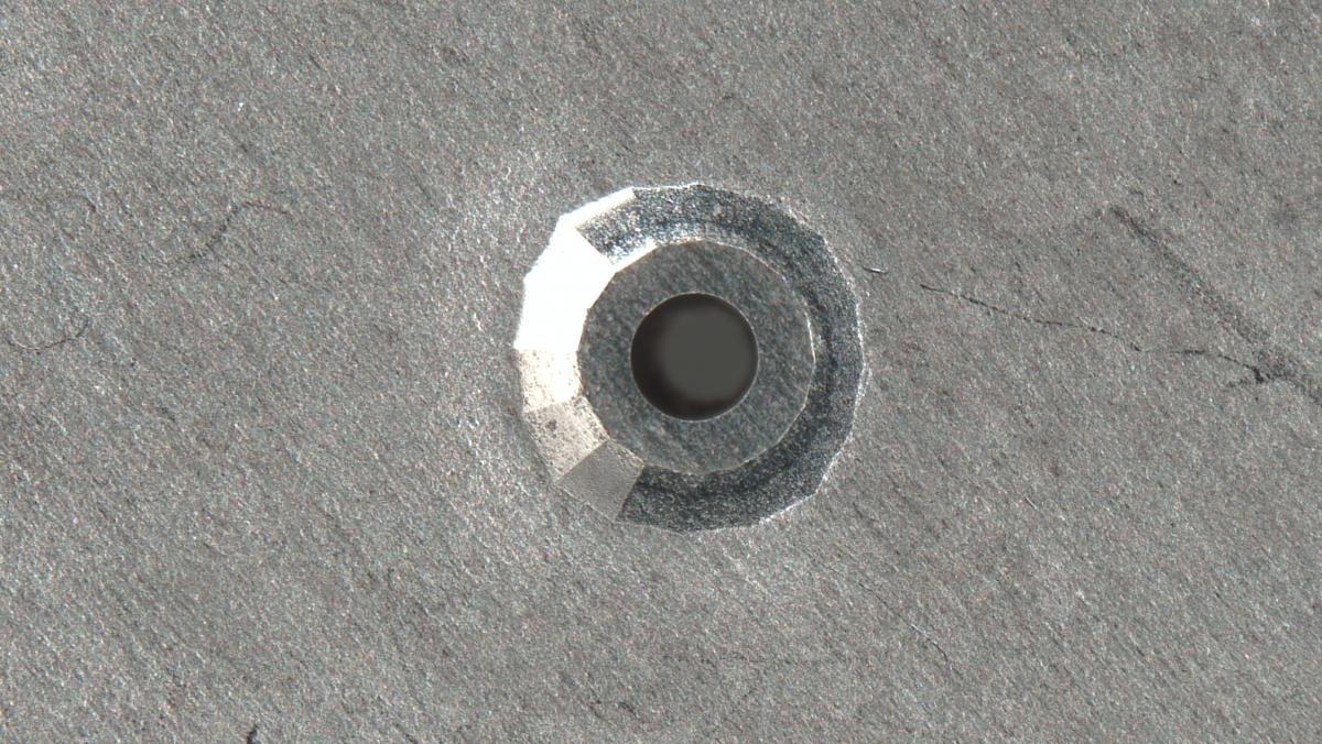
g) Fill the bath with paraffin again and repeat steps above. This time you want to drill all the way through though, so leave the drill going until you see bubbles coming from underneath. Leave the drill going for about another 10 divisions once you see bubbles in order that the hole produced is nicely cylindrical. Now stop the drill and move the table back to 0. Move the drill out of the way, suck the paraffin/kerosene out and remove the gasket.
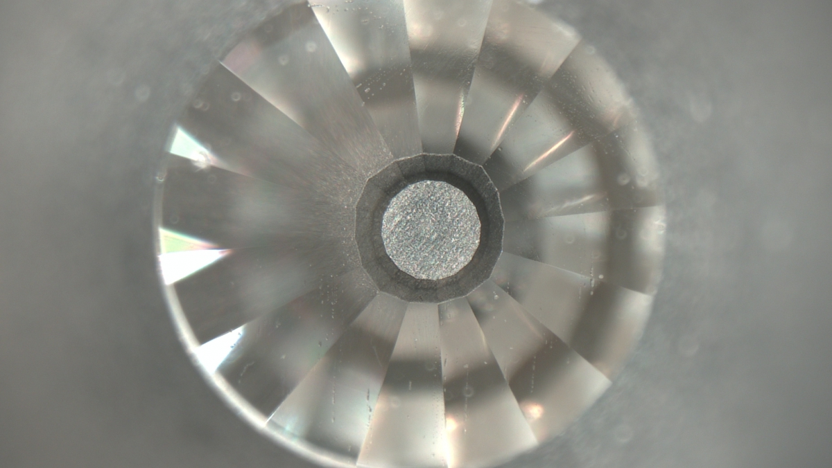
10) Clean all the dirt and paraffin off the gasket using a cotton wool bud, scrubbing it hard using ethanol to make sure the hole is clean. Next check that the hole is in the centre of the indent on both sides of the gasket using the microscope.
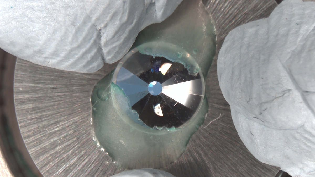
11) Now use Blu-tac to stick the bottom half of the cell under the microscope with the diamond in the centre of the crosshairs. Then put the gasket on top making sure that the hole is lined up over the middle of the diamond culet. The gasket should be placed in the same position and orientation as it was during step 4 onwards.
12) Put the top half of the cell on and make sure that the hole is in the middle of the culets on both sides. The cell is now ready for the ruby and sample loading.
Loading a Sample
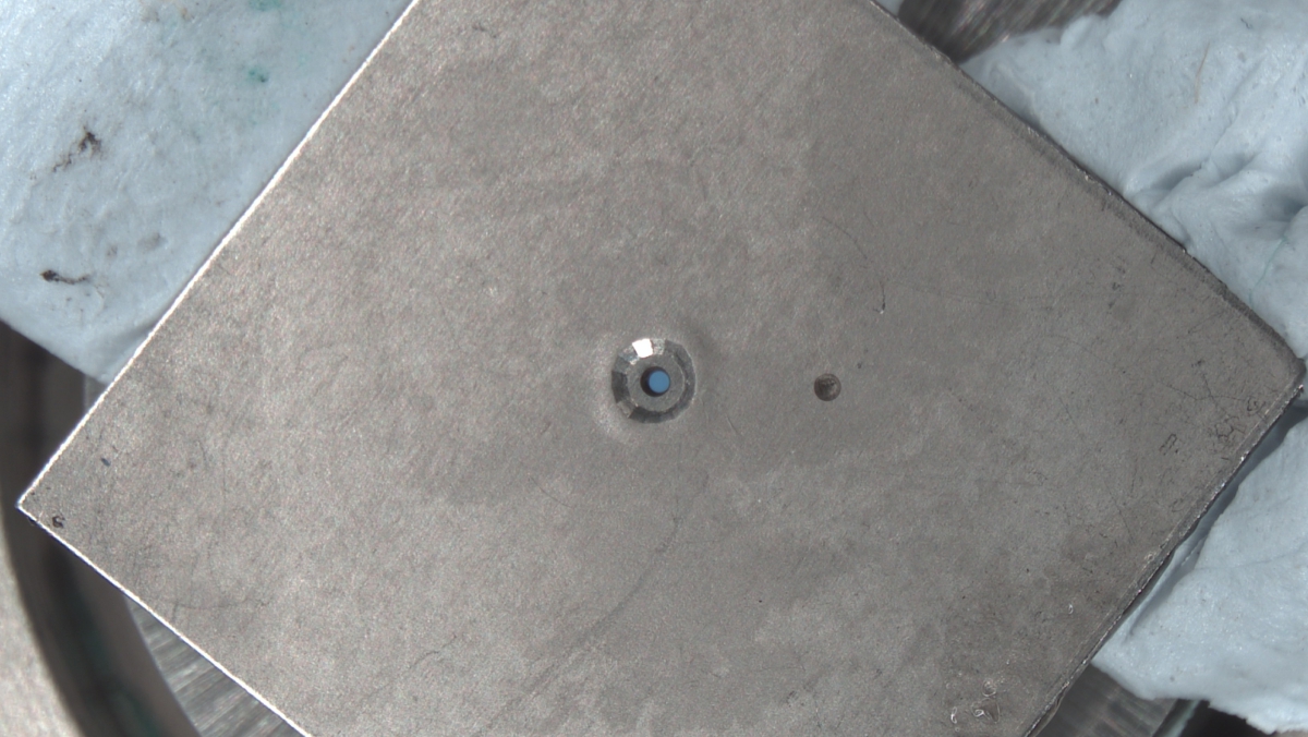
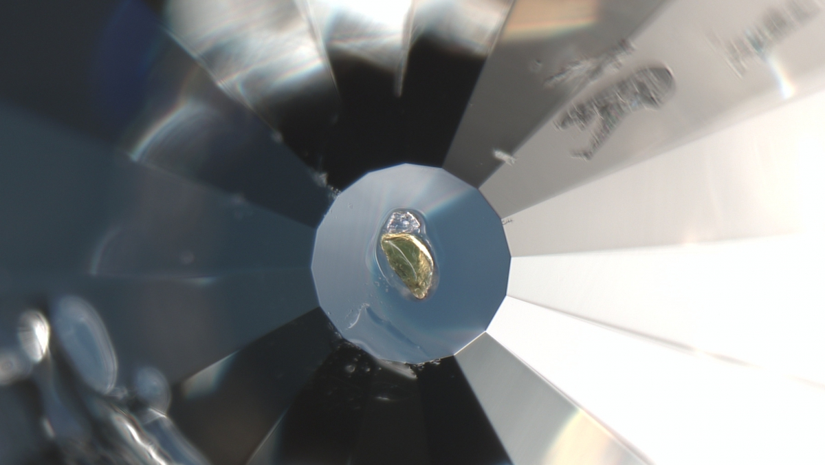
1) Now that the gasket has been drilled and everything is aligned, the next thing to do is place a ruby chip on the top diamond.
2) Firstly, using the microscope, place a blob of KF gel/grease on the culet of the diamond on the top half of the cell. Then, using the other microscope, find a small chip of ruby from the box and place it in the blob of gel, keeping it as central on the culet as possible.
3) Next, look at your sample crystals under a microscope and select one which looks nice but isn’t too big, as it needs to fit inside the gasket hole. Pick your crystal out and place it in the blob of gel next to the ruby chip.
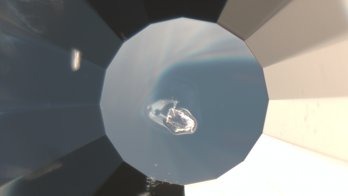
4) Put the two halves of the cell together and check that the crystal is in the gasket hole, preferably in the centre, by looking through the cell with a microscope.
5) Now you can choose the liquid to go in the cell. There are a number of possibilities here, the aim is to pick a liquid which does not react/dissolve your sample and remains hydrostatic to as high in pressure as possible.
It is important that the safety implications for the solvents is known prior to testing your sample.
6) When a liquid has been chosen, a drop of it is placed in the gasket hole with a dropper and the top of the cell is pushed down firmly, keeping downwards pressure on the top of the cell. With pressure still being exerted on the top of the cell, put in the screws and tighten them to “finger tightness”.
7) Next check the cell under the microscope to make sure that the liquid is in the cell and that the crystal has not been washed away.
8) The pressure of the cell then needs to be checked using the pressure kit (see instructions in the next section).
9) The sample is then ready for data collection and you now need to set it up on the chosen diffractometer.
Using the Pressure Measurement Setup
1) Place the loaded cell into the metallic cell holder, with the front of the cell facing outwards, and tighten into place using appropriate hex key.
2) Place the cell holder onto the platform with the front of the cell facing towards the mirror setup, ensuring that the holder is positioned correctly (pushed against the back left corner of the platform).
3) Turn on the light box to the left of the mirror setup and lower the mirror closest to the computer monitor, ensuring not to misalign the mirror position, and examine the placement of the cell using the VLC Media Player, ensuring the video camera is switched on. On start-up you will have to point the software towards the software (Media => Open Capture Device => Play, keeping the default settings), . Move the platform until the DAC sample chamber is visible and in focus on the VLC player
4) Turn on the laser light, and check that the laser light is positioned over the ruby chips. DO NOT LOOK DIRECTLY AT THE LASER LIGHT.
5) Turn off the light box and raise the mirror closest to the computer monitor, so that the fluorescent light is now directed onto the detector.
6) Load up the Spectra Suite software and press the play button in order to start the fluorescence measurement collection. The two peaks at around 692 nm and 694 nm represent the fluorescence peaks from the ruby chips, with the specific wavelength of those peaks altering with the applied cell pressure. We usually the larger peak at 694 nm as the peak for pressure measurement, due to possible merging of the two peaks at higher pressures. If these peaks are not visible, or are very low intensity, make slight adjustments to the platform position until the maximum peak heights are achieved.
7) Click on the spectrum area to open a toolbar at the bottom of the screen, which includes a ‘configure peak’ button. Click it, and set an appropriate baseline value so that the tallest peak only will be picked. Set the ‘scan average’ value (top left of the screen) to 5-10 or pause the collection.
8) Take a note of the peak wavelength, shown at the bottom of the screen, and input this value in the appropriate box in the open office spreadsheet (which can be found on the desktop), which will then calculate the cell pressure. If necessary, and for good practice, you can measure the corresponding wavelength for ambient pressure; you do this by repeating the above process for the ruby DAC (which can be found close to the mirror setup) – this contains just a large piece of ruby without any pressure transmitting media. Fluctuations in temperature in the lab can cause the ambient pressure wavelength to drift slightly.
9) If you want to do further increases in pressure, you can leave the DAC in the metallic holder while the screws are tightened; this will save you having to realign everything again.
10) When leaving the lab, ensure that the computer and all other equipment, including sparker eroder and microscopes that you might have been using previously, are switched off.
NOTE: Take care during pressure measurements and lab cleaning to not hit and misalign the mirror setup.